Audio Intro:
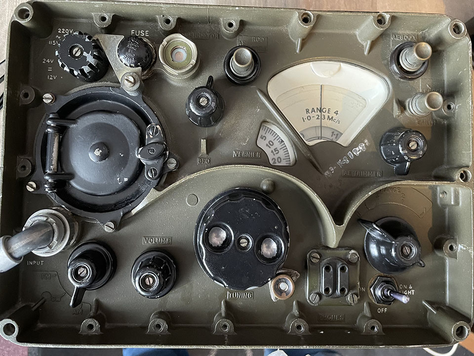 This is my Reception Set R209/2/B army communications receiver. The radio is a British design from Mullard, London, and was made under licence in Belgium. This radio is a later variant of the R209 MK II receiver. The date on the IF cans reads 26th September 1956. Bear in mind that the radio might have been manufactured some time after that date. I’ve not owned one before so I’m working my way around the chassis. Frequency coverage is 1MHz to 20MHz. The receiver consists of an RF amplifier, separate mixer and oscillator valves and three IF stages. This version is 230, 115, 24 or 12 Volts. Strangely, it receives FM as well as AM. It does have a fault which I’m looking into. Volume is very low on AM but there’s plenty of loud hiss on FM. I’m in the process of studying the circuit to work out the discrimination and detector set-up. For your interest, there are two videos at the bottom of this page.
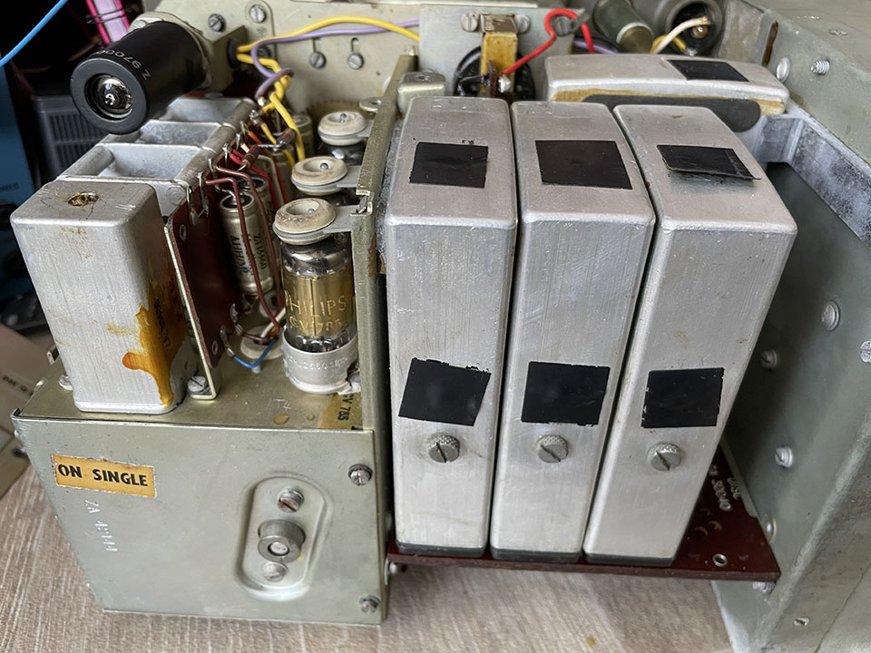
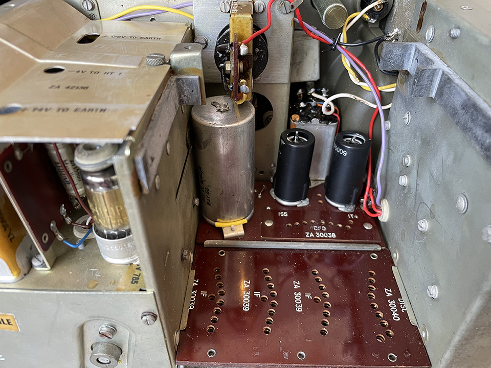
The design is interesting. The three IF stages are separate plug in units, all identical. The detector and BFO are also separate plug in units. See photos. The AGC voltage is taken from V10, one of the push-pull audio output valves. Take a look at the manual.
From what I understand, the R209 was used in conjunction with the WS42 transmitter. Apparently, the WS42 was discarded due to its excessive weight. How true this is, I don’t know.
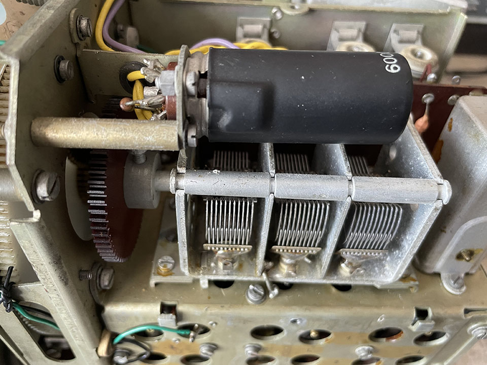
Left, bottom view. Centre, top view. Right, tuning gang.
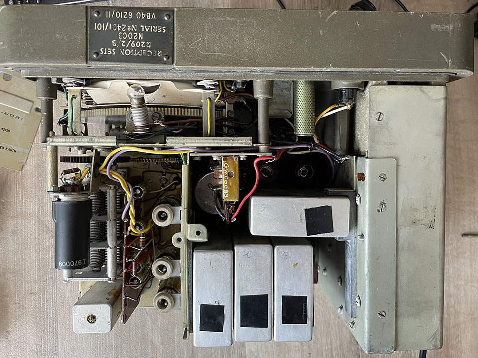
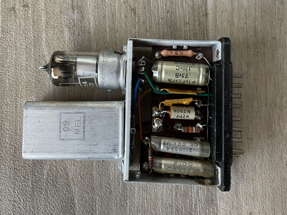
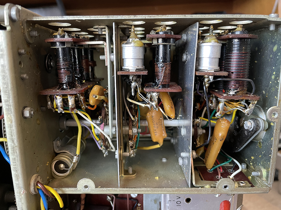
Left, plug-in assemblies. Centre, detector unit. Right, coil pack.
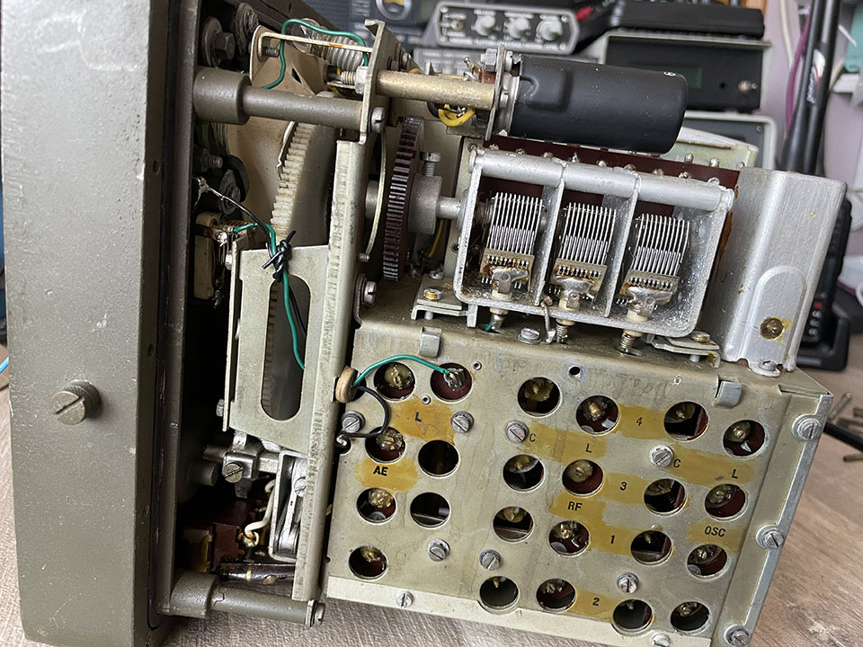
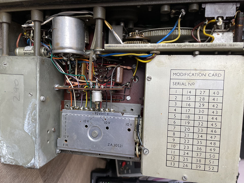
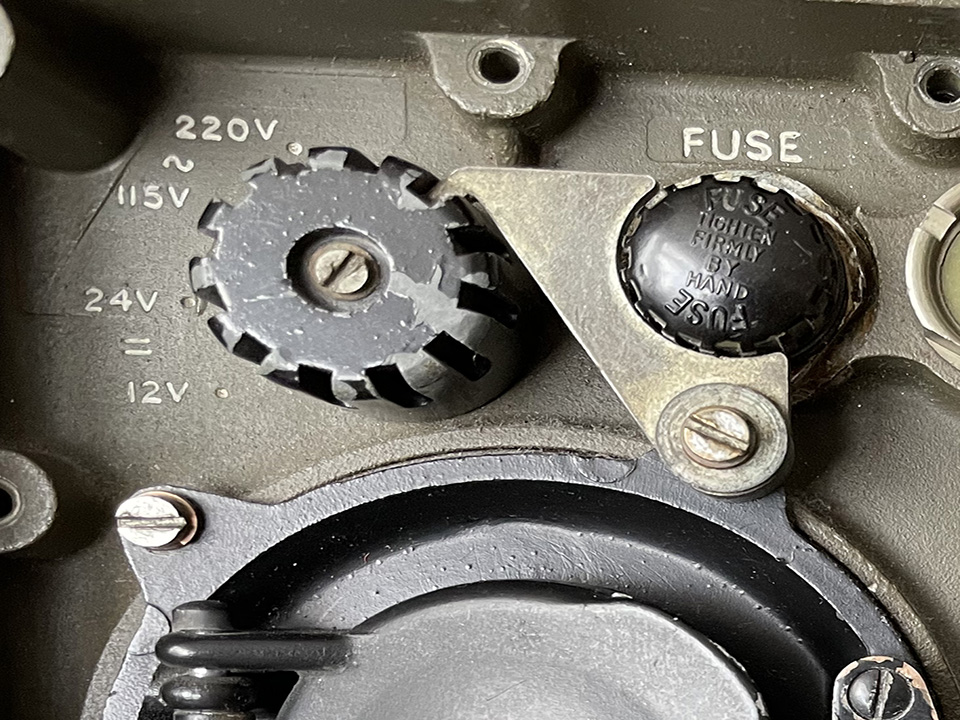
Left, voltage selector. Centre, plug-in units removed. Right, coil pack cover removed.
The Power Supply:
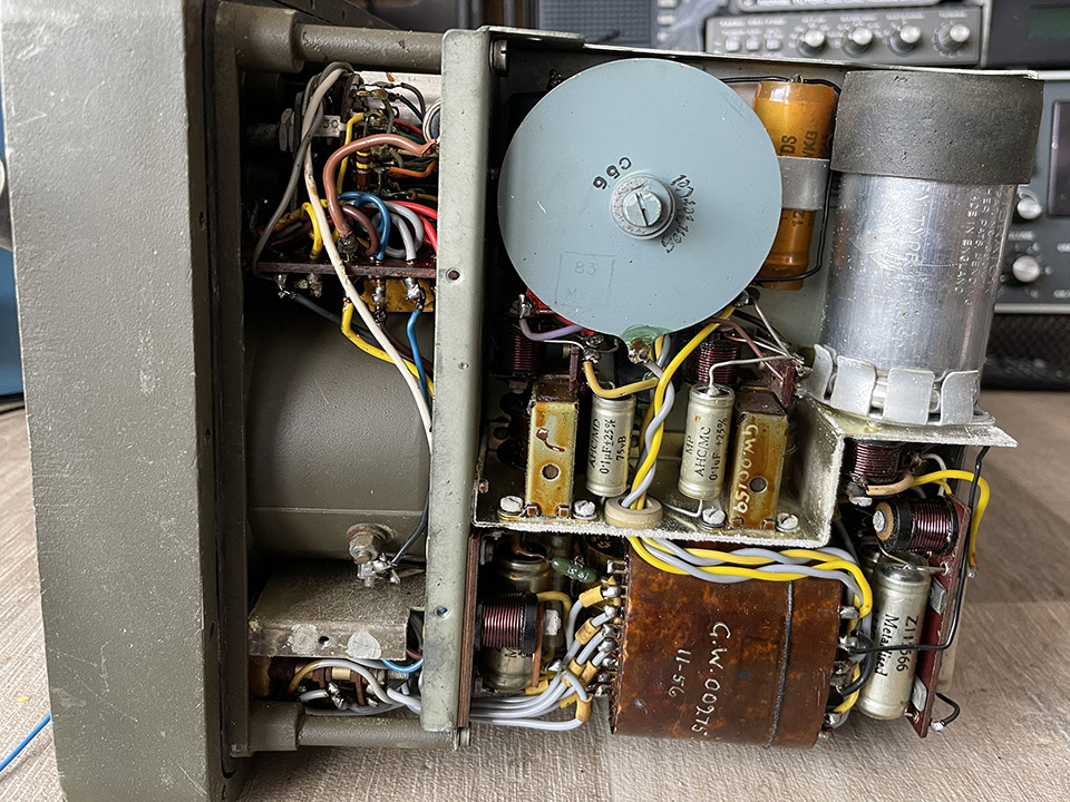
The power supply is shown below. The radio is running on 230 Volts at the moment but it can be switched to 115V 24V or 12V. Notice the selenium rectifier. It works, so I won’t be replacing it with silicon diodes. The vibrator is top right. Good old technology that is still working today. I doubt that anything built these days will still be working 70 years from now.
Clues as to the date of manufacture:
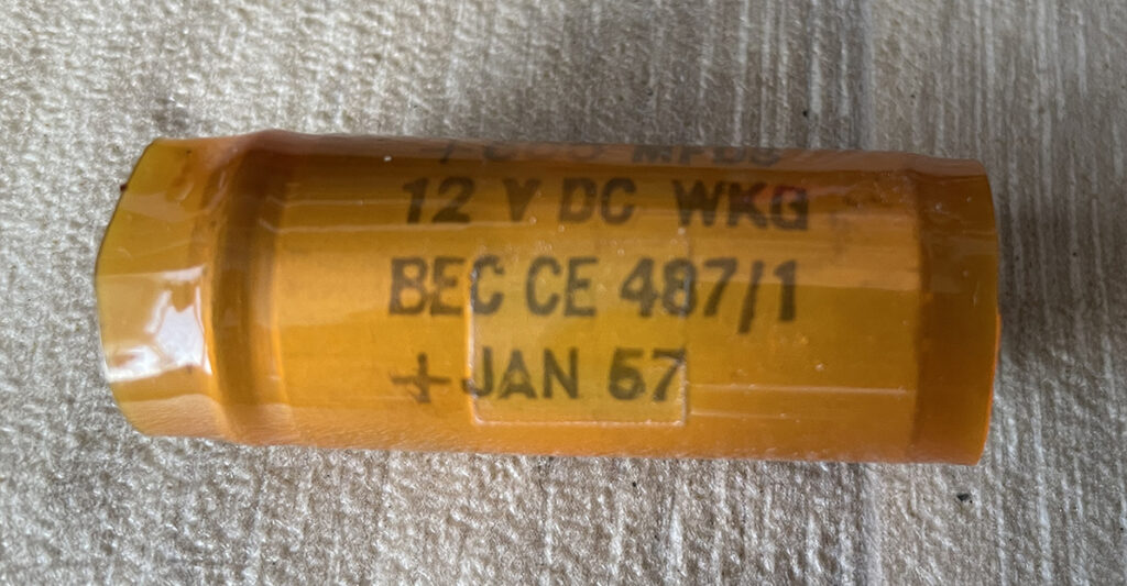
I replaced an LT smoothing capacitor, 500uF 12 Volt, which had a date stamp, January 1957. Electrolytic capacitors are often dated, which is a great help in determining the radio’s year of manufacture. The date on the IF cans reads 26th September 1956. The mains transformer is marked 11-56.
Specification:
The R209/2/B reception supersedes the R209 MK II.
Aerial connections for end-fed wire, rod or dipole.
Frequency range in 4 bands 1.0-2.3 MHz. 2.3-5.6 MHz.l 5.5-12.5 MHz. 12.l0-20.0 MHz.
Modes AM/CW/FM.
In FM mode, V8 acts as an IF limiter and the diode section is the discriminator.
The audio stage is push-pull, with a 10 ohm speaker and a socket for two 150 ohm headphones.
The set has no IF signal out socket, unlike previous versions. In its place is the on/off switch.
It has a new PSU, 12 volts or 24 volts battery. Also, mains-supply 115 and 220 volts.
Aerial connections:
The receiver has two terminals marked ‘earth’ and ‘AE80’ ohms for a dipole. There is also a high impedance connection marked ‘rod/wire’.
Valve line up:
| V1 | CV131 – EF92 | RF amp |
| V2 | CV782 – DK91 | Mixer |
| V3 | CV284 – 75B1 | Stabiliser |
| V4 | CV785 – DF91 | Local oscillator |
| V5 | CV785 – DF91 | IF amp |
| V6 | CV785 – DF91 | IF amp |
| V7 | CV785 – DF91 | IF amp |
| V8 | CV784 – DAF91 | Detector AM & CW |
| V9 | CV785 – DF91 | Audio output |
| V10 | CV784 – DAF91 | Audio output & AGC |
| V11 | CV784 – DAF91 | BFO |
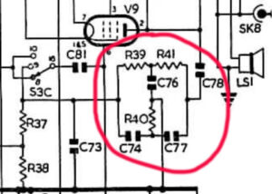
The unusual audio push pull output stage:
You’ll notice from the circuit diagram there is no phase splitter triode or transformer in the audio output stage. This is an old and interesting design known as self drive push pull. The signal is applied to the control grid of V9 and taken from the screen grid of V9, via coupling capacitor C80, to the control grid of V10. So, V9 is driven by the input signal, and V10 receives its drive from the signal developed at the screen grid of V9. Apparently, this was a cost-saving design. From what I understand, distortion can be a problem if this design is used in hi-fi amps. However, in a communications receiver, distortion isn’t noticeable. You’ll also notice that v10 incorporates a diode. The supplies the audio-derived AGC voltage which is applied to the RF amplifier and the first and second IF stages.
CW and SSB reception:
 When switched to CW, a filter is introduced in the audio output stage to, as the manual put it, ‘peak the beat note at 950c/s’. See diagram and the manual. SSB sounds good to my ear using the BFO. I’ve had suggestions about changing the filter circuit and adding this and that to the radio but I won’t be modifying anything as I like to keep vintage gear as original as possible. I will be replacing all coupling and decoupling capacitors, of course. The radio is incredibly stable with hardly any drift when resoving SSB.
Push pull output and AGC diode:
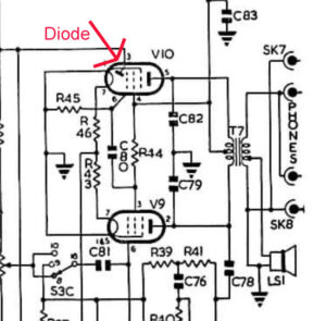 The push pull output stage is shown here. Note the diode in V10. This is for audio-derived AGC. An unusual way of producing the AGC voltage but, it works. AGC is applied to the RF amp and the first and second IF stages.
Coupling decoupling caps:
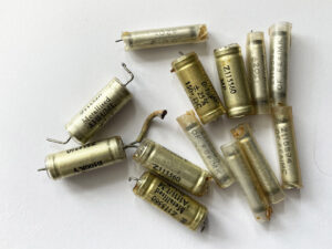 I’ve started to replace all the old capacitors. The radio improves with each one I change, thirteen so far, and there are many more! Unfortunately, some are hidden and are difficult to get to. But, they have to be replaced.
Update: I’ve now replaced twenty-one capacitors. And there are still more to replace!
Update 4/6/24:
Ive now got the radio working, see video. Using the BFO, it resolves SSB surprisingly well. Another surprise is minimal drift. Unlike my Marconi CR100, which has to be retuned several times as it warms up. The next job is alignment, which has been got at by a twiddler!
Update 8/6/24:
I’ve had to make a second video because… there’s been an unfortunate development. In fact, it’s a highly embarrassing development!
Update 29/7/24:
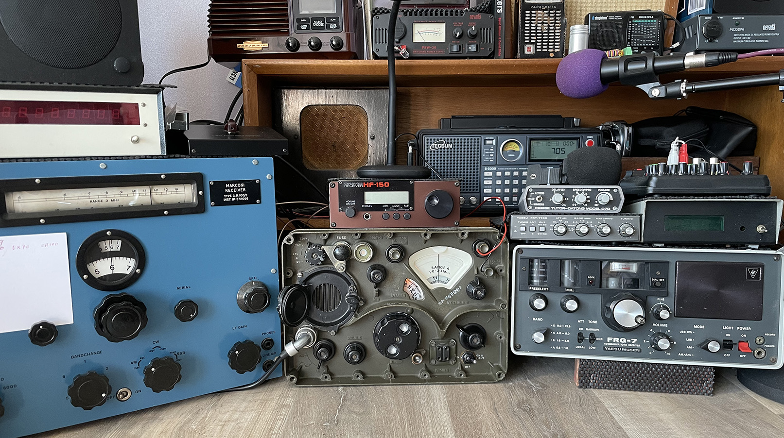
The work is complete and the radio is now in use between the Marconi CR100 and the Yaesu FGR-7. I’ve really enjoyed working on this radio, and I’m going to enjoy using it. I’m used to working on 1940s domestic radios, so it was a nice change to go modern… well, what was modern back in 1957. Next on the bench will be my National HRO receiver.
For your interest, the Service Manual is here.