The AR88D communications receiver was manufactured by RCA in America from 1941 to 1945. Many were sent to the UK and Russia. There were two versions, the AR88D and the AR88LF (low frequency version). The circuit comprises two RF stages (6SG7), a first detector (6SA7) and oscillator (6J5), 3 IF stages (6SG7), second detector and AVC (6H6), noise limiter (6H6), BFO (6J5), AF amplifier (6SJ7) and power output amplifier (6V6GT), a power supply (5Y3GT), and regulator (VR150). They are all metal valves except for the audio output, rectifier, and regulator.
Note: In America, the mixer or frequency changer stage is called the ‘first detector’.
Update 8/4/2025:
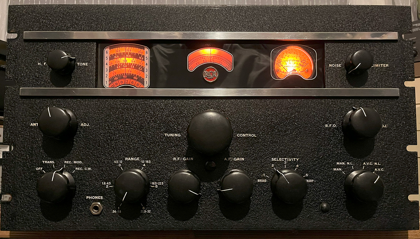
I now own an AR88D which I will be working on as soon as I can find space for a very sturdy table. The receiver weighs 98lbs, that’s 7 stone! At the moment, the radio is standing on a Black & Decker Workmate. The photo below shows how clean the front panel is. This is a lovely example of the iconic AR88D communications receiver. The cabinet is also in excellent condition.
The chassis, top view:
The front panel is in pristine condition but the chassis needs a good clean. Rather than a dial drive cord for tuning, which can cause backlash, the radio employs a gear train with excellent flywheel action. You’ll notice that the alignment tools are missing.
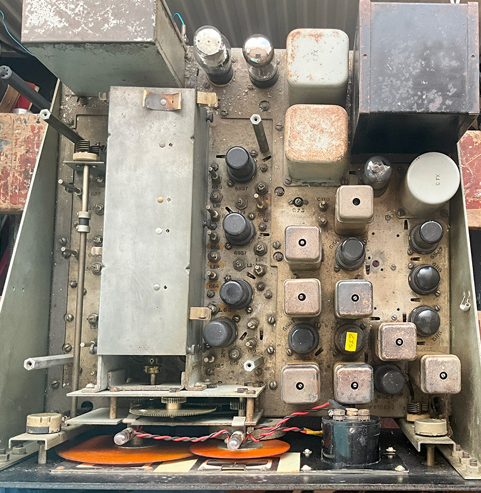
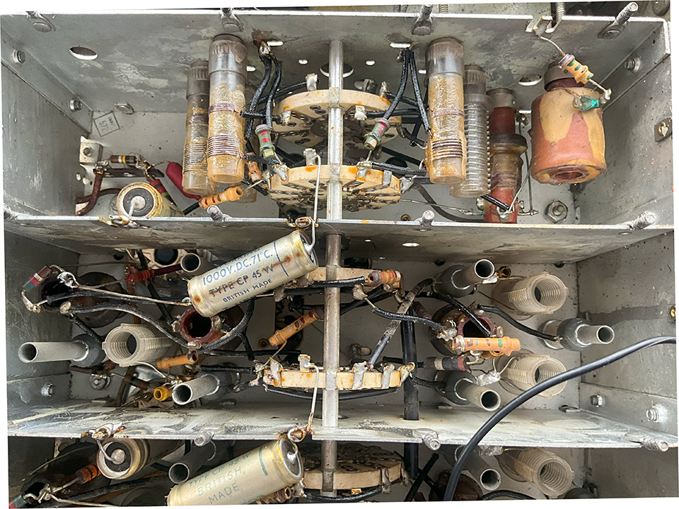
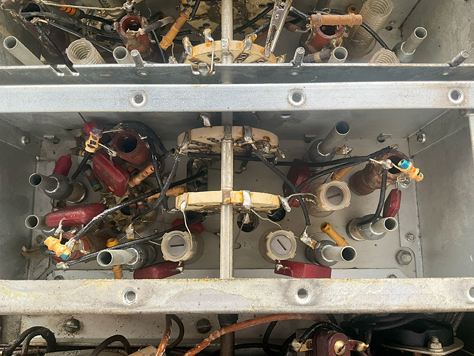
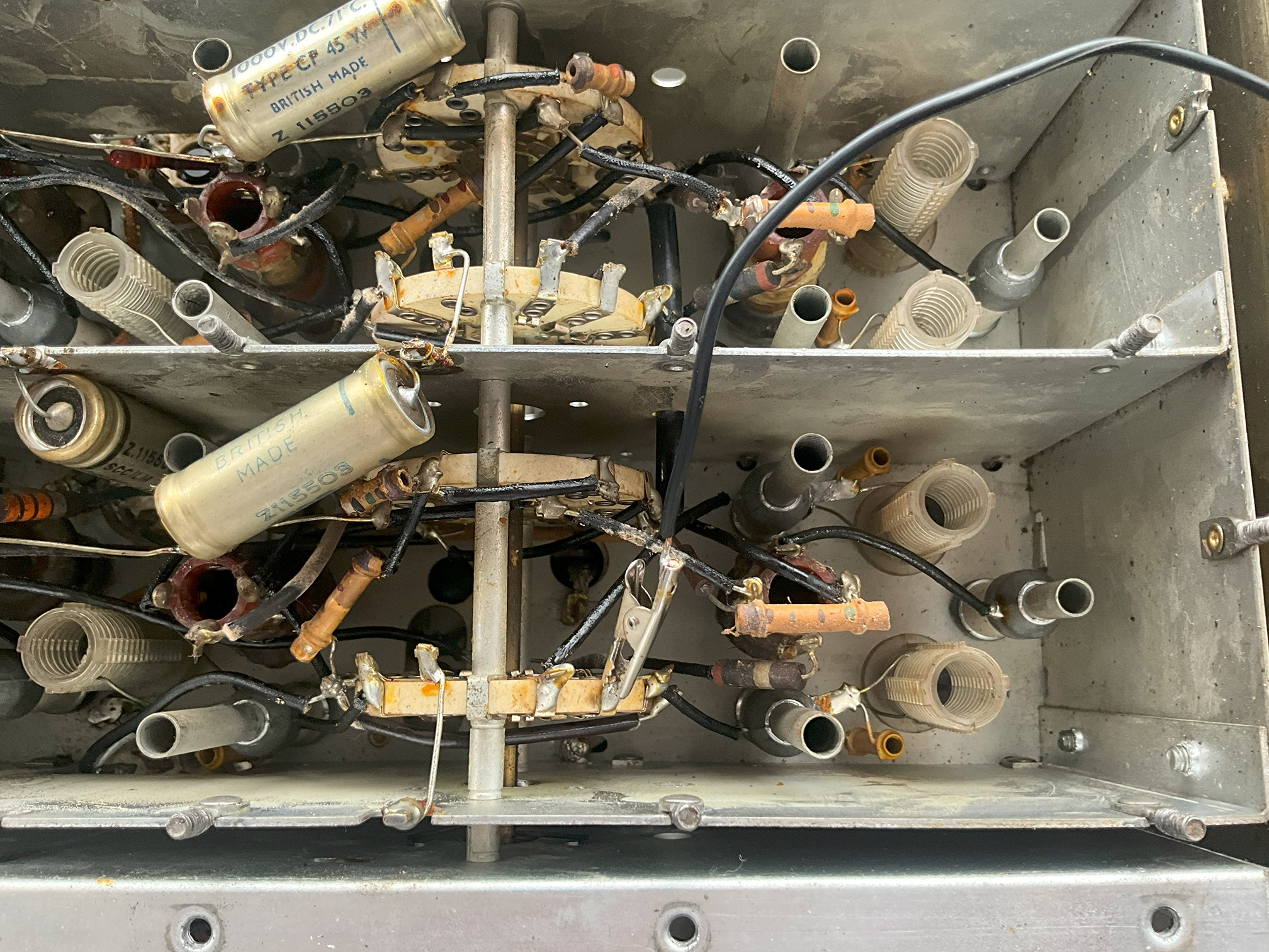
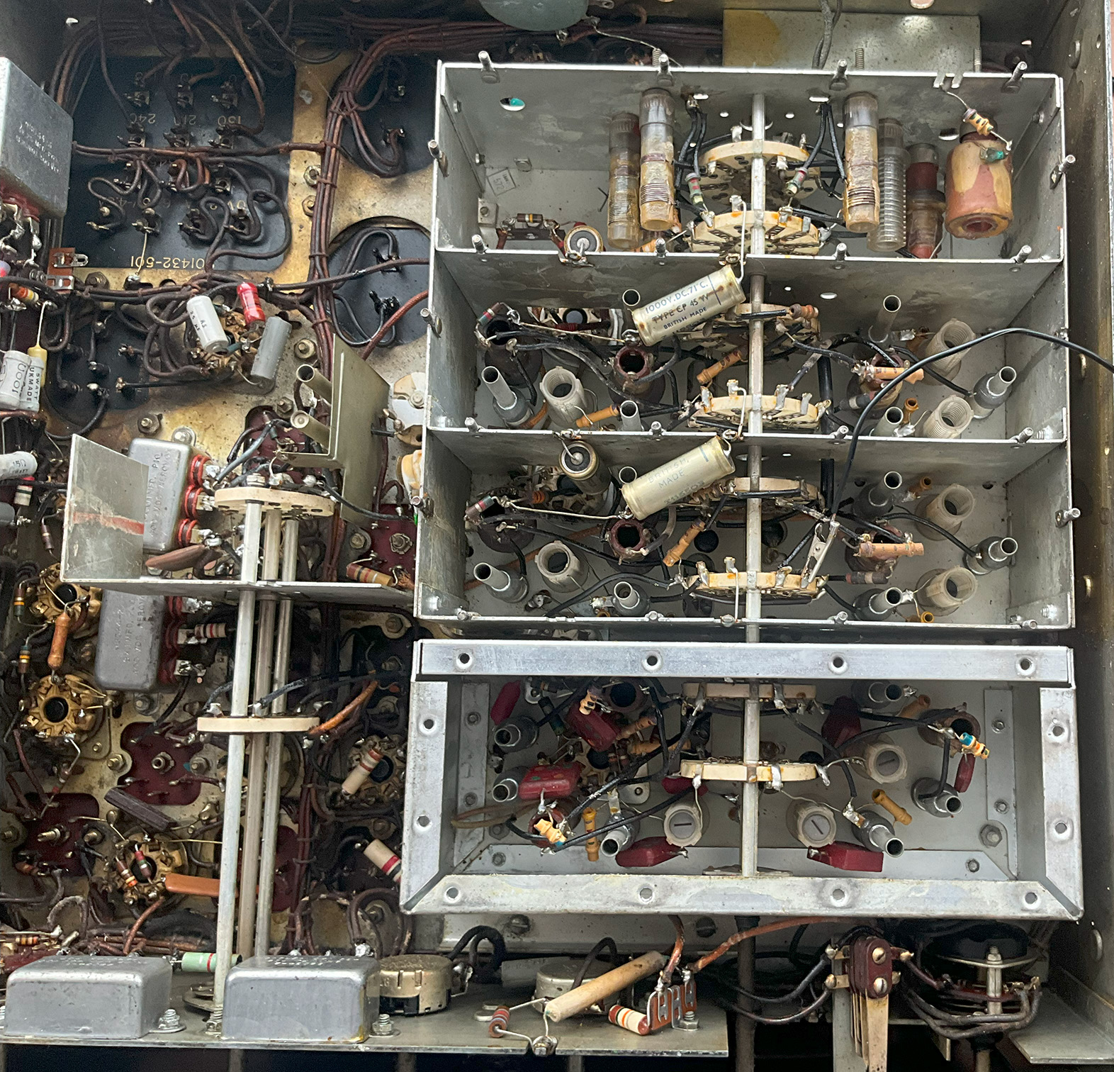
The photos below show the various RF stages:
Update 13/4/25:
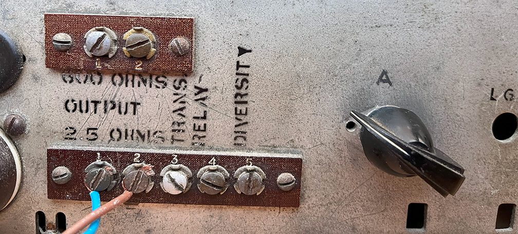
The receiver is deaf, to put it mildly. Initial investigation points to the second RF amplifier stage. Only strong signals can be heard and the S meter barely moves. However, connecting the aerial directly to the mixer brings up signals considerably, see photo below, and the S meter reads half scale on strong stations.
It’s not easy following the circuit diagram as there are many switch connections. Also, the Americans draw circuit diagrams upside down. I’m used to the HT rail (B+) and valve anodes shown at the top of the diagram, not the bottom. Having said that, I’m sure the Americans would say that the British draw circuit diagrams upside down.
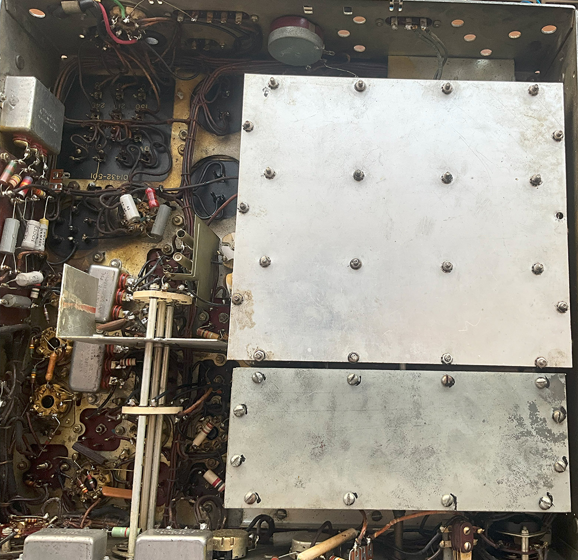
Bottom covers replaced:
Update 15/4/25:
On checking valve voltages, I discovered that the second RF amp screen grid volts were very low. Replacing the 33K screen feed resistor solved the problem. Signals increased significantly but the receiver wasn’t as lively as it should be. I fitted a new first RF amplifier valve (6SG7). The receiver is now bursting with life on all bands!
S meter adjustment:
I’ve now discovered that the control on the rear panel (R21 not shown on the circuit) is for S meter adjustment. I’ve set the S meter up as per instructions and it’s now reading properly.
1/ Disconnect aerial and short circuit aerial terminals.
2/ Connect AC voltmeter across speaker terminals.
3/ Set AF gain to maximum.
4/ Adjust RF gain for 0.5 Volts.
5/ Adjust R21 until S meter shows extreme left of scale.
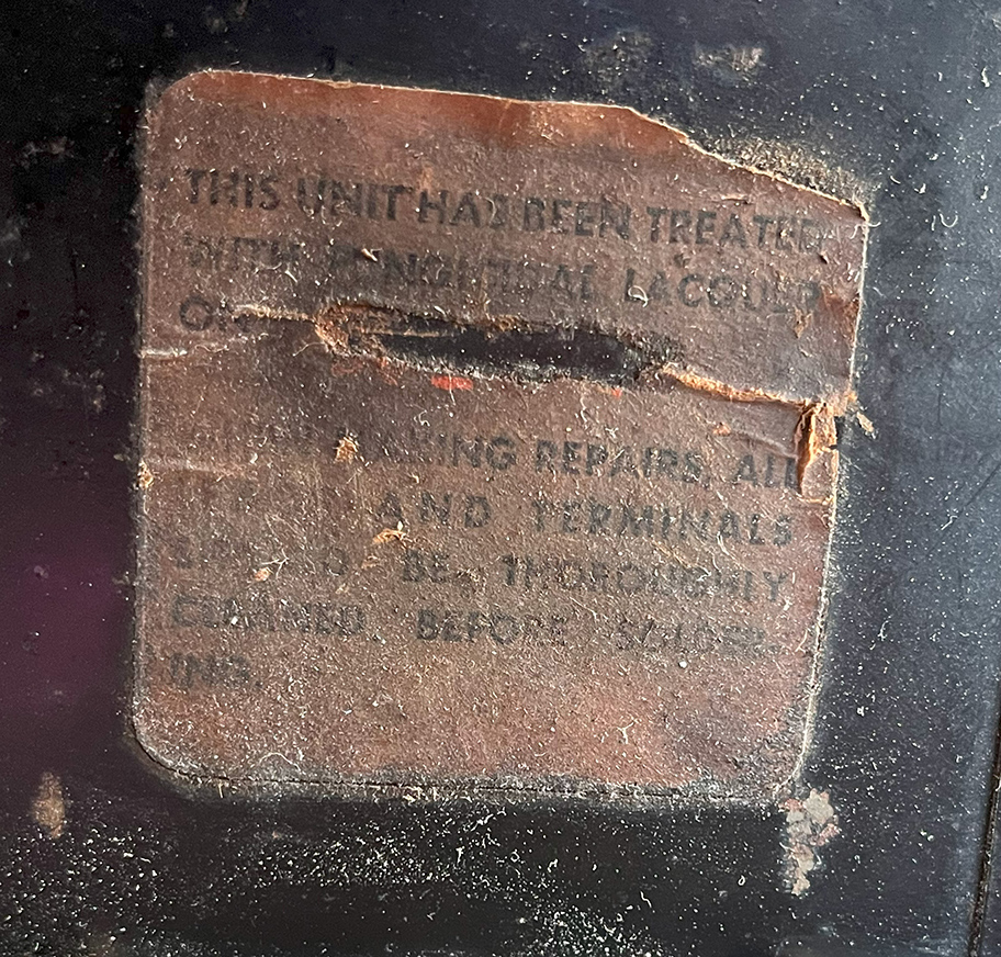
Interesting Label:
There’s a label attached to the mains transformer, see photo below. I can just about read: This unit has been treated with — lacquer. Before making repairs all —- and terminals must be thoroughly cleaned before soldering.
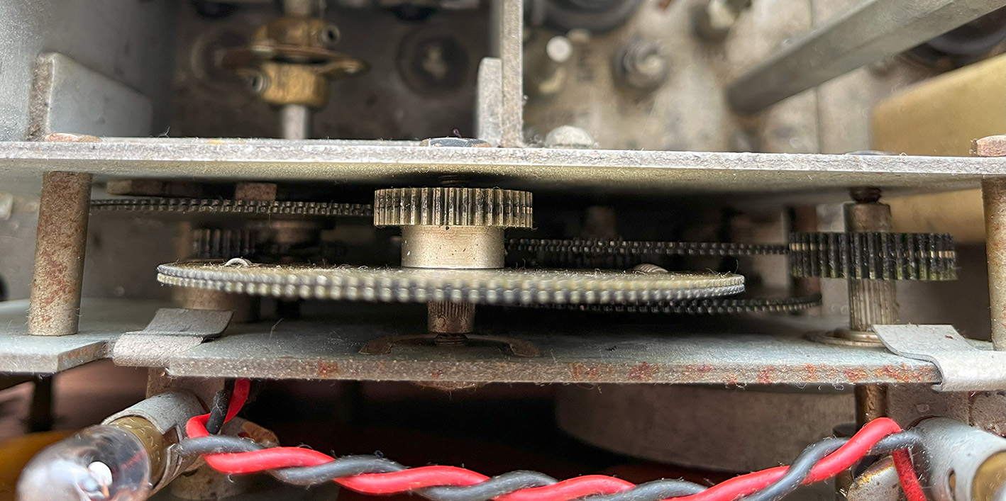
The gear train:
No dial drive cord, no backlash, no slack… just decent gears from the days when things were made properly.
A little history:
Apparently, many years ago, the receiver came from GWM Radio Ltd. Portland Road, Worthing. Yogi carried out some work on the radio, which included replacing many capacitors and resistors.
Video – part one:
Video – part two:
Thanks to Brian for the Shortwave Magazine Article 1958: Getting the Most From Your AR-88