Manuals and articles at bottom of page.
The mystery of my National HRO receiver:
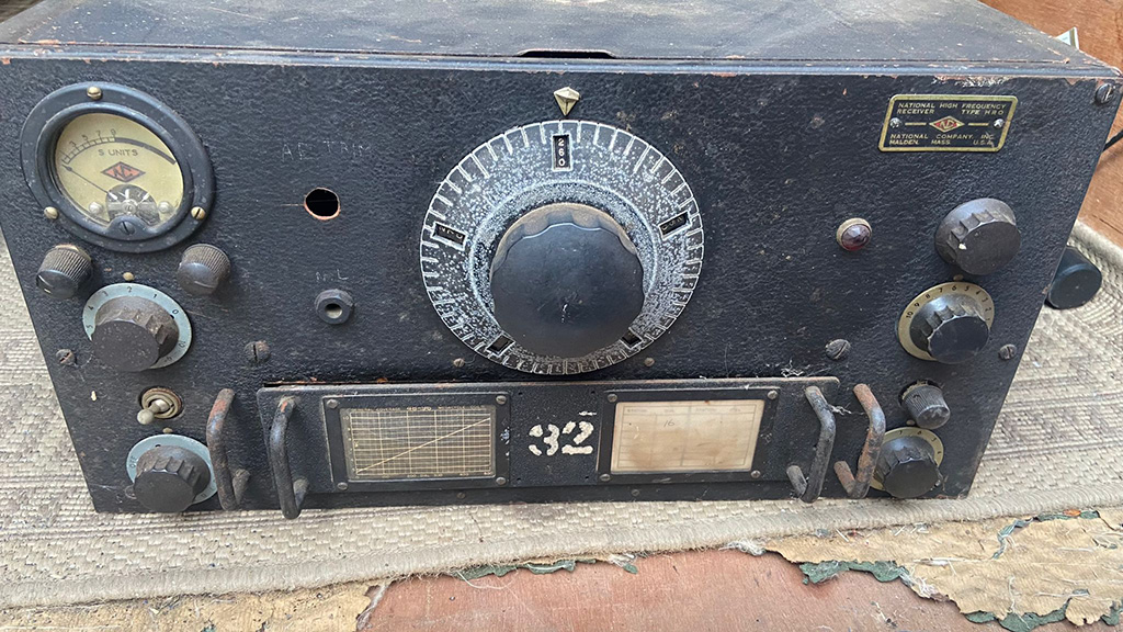
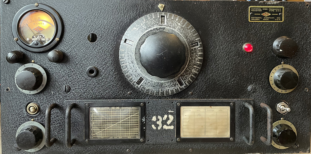
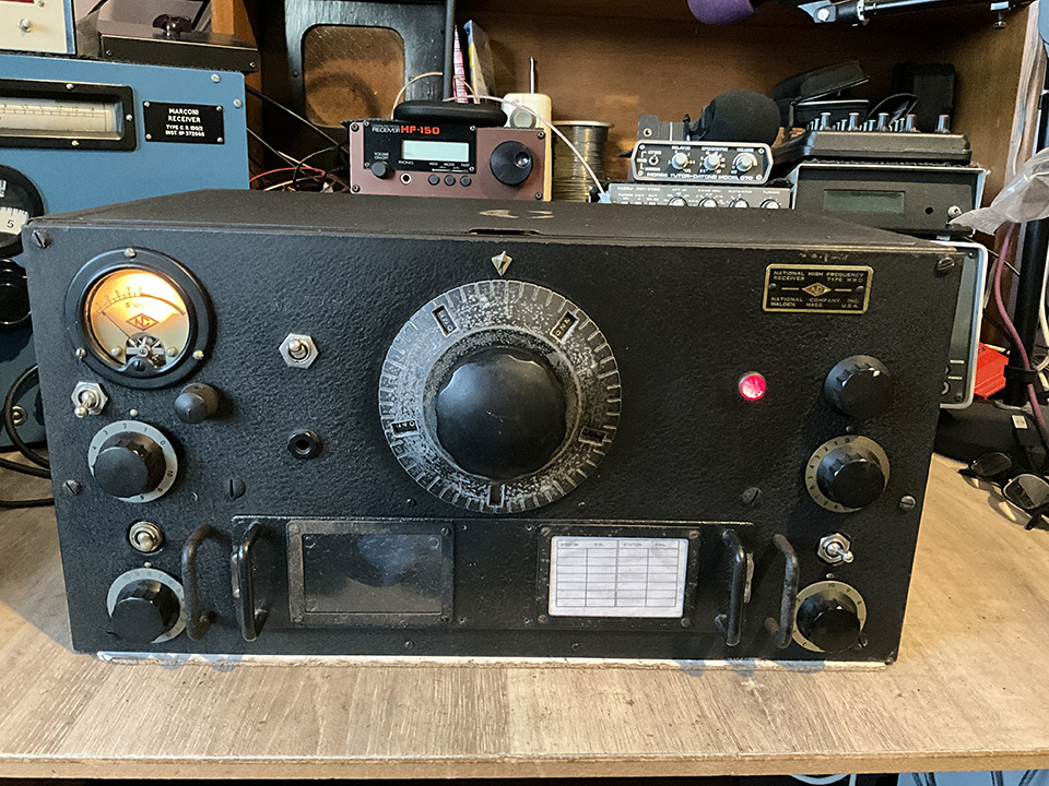
I have a National HRO 5TA1 – 5A1 – R106 mk1 mk2… I have no idea which model it is. I’m hoping that, when I finally finish this page, I will have solved the mystery and the radio will be restored and working well. Unraveling the mystery begins here… When the receiver is fully restored, I hope to use it in conjunction with my HF valve transmitter.
The radio was given to me by my good friend, Roy, G4WTV. There’s no power supply with it, but that’s not a problem. The 6.3 volt heater valves have been replaced with 12.6 volt. The radio appears to be complete but, as I’ve never worked on an HRO before, I’m spending a little time getting to know the layout. It’s going to take me some time to determine the model number. It would have helped had it been on the front plate, which just says HRO. For progress reports, see Updates at the bottom of this page.
The mystery deepens:
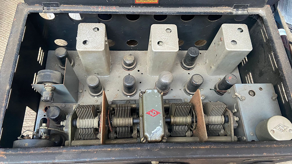
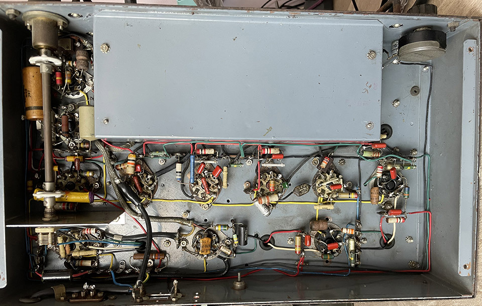
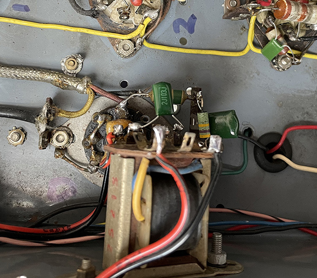
Below is an under-chassis view. Someone has fitted a small audio output transformer which is wired incorrectly. Originally, the extension speaker housed an output transformer. That’s an odd arrangement by the manufacturer but they must have had a good reason. The power lead has been cut off. The volume control is seized solid. The RF gain pot is open circuit and has been wired incorrectly. A extra pot has been fitted to the front panel. The wires to the indicator lamp have been cut. There are no valves with top caps. Usually, in this type of receiver, the RF and IF valves have their control grids connected to the top caps. I can’t find the audio output valve. This would normally be a pentode or a beam tetrode such as a 6V6, but there isn’t one in the radio. There’s a B36 audio double diode in its place. There’s quite a lot of work to do but it will be worth-while.
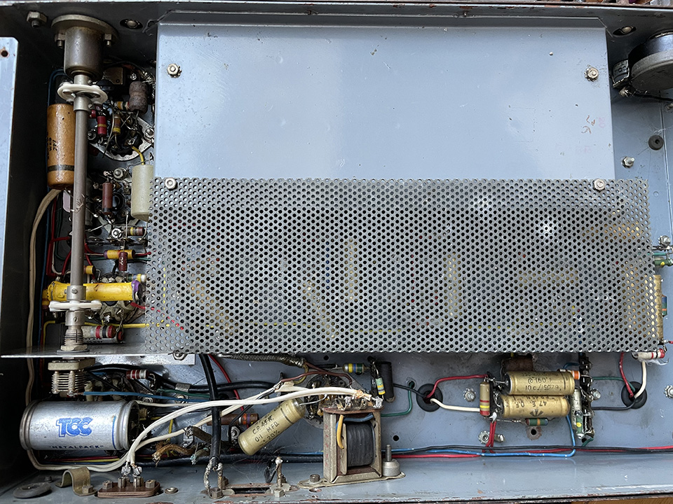
Below… audio output transformer removed. Decoupling capacitors replaced. Power lead fitted. The journey continues.
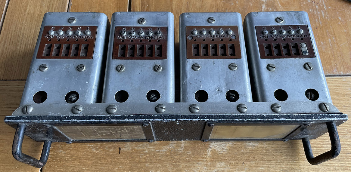
Coil Packs:
The coil pack I have is shown below. It covers 280 to 960KHz.
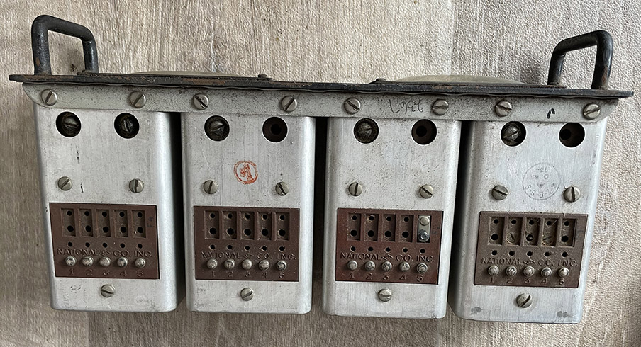
| Type J = 50 – 100KHz Type H = 100 – 200KHz Type G = 180 – 430KHz Type F = 480 – 960KHz. Type E = 900 – 2050KHz Type JD = 1.7 – 4.0MHz Type JC = 3.5 – 7.3MHz Type JB = 7.0 – 14.4MHz Type JA = 14.0 – 30.0MHz |
 |
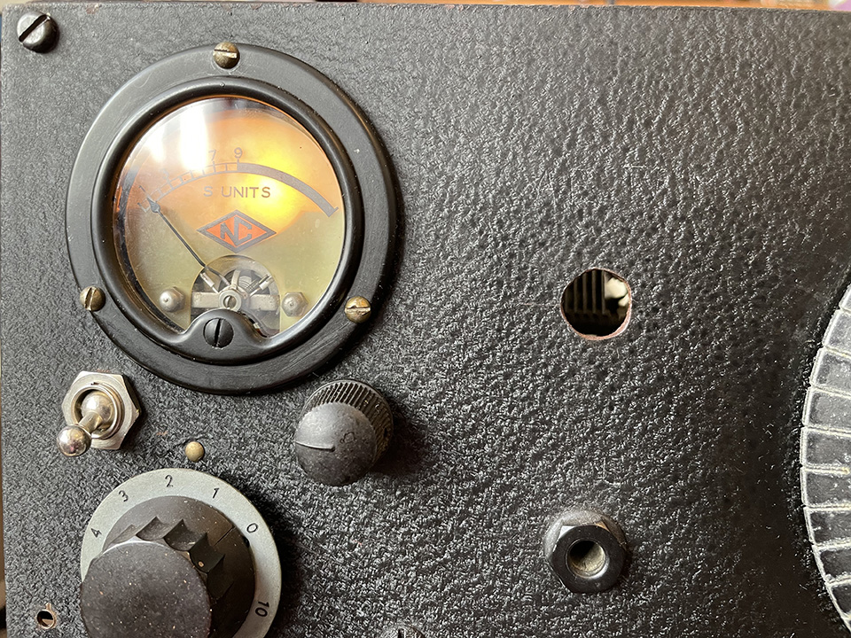
The S-Meter:
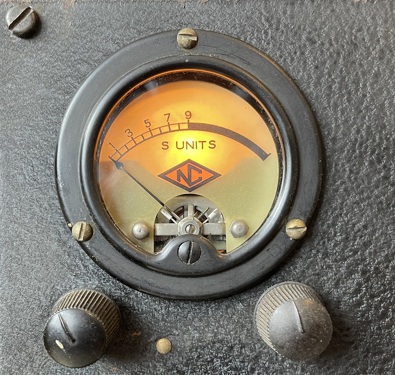 I’ve managed to remove the S-meter for cleaning. The moving coil meter worked but the glass had been pushed in, as is often the case with these old panel meters. There’s a hole in the back which is where a small holder and bulb was once fitted. I’ve now fitted a bulb and holder.
Although the radio isn’t working yet, I’m carrying out some small jobs just to get them out of the way. There’s still some confusion in my mind as to which model this is. There’s also some confusion about the modifications but I’ll get there in the end.
Unfortunately, the small spigot to zero the S meter needle has been broken so the adjustment on the front of the meter does nothing. There’s not a great deal I can do about that. I will zero the needle before reassembling the meter.
Video one on the HRO:
Video two on the HRO:
Video three on the HRO:
In this video, I make some real progress. At last, I’m getting somewhere!
Video four on the HRO:
The radio is now working!
Video five on the HRO:
More progress on the HRO.
Video six on the HRO:
More progress on the HRO.
Video seven on the HRO:
More progress on the HRO.
Video eight on the HRO:
The HRO power supply.
Updates will be listed here as I make progress:
16 Aug 2024:
The radio appears to have had a factory modification. The valves do not have top caps but the control grid leads have been routed to the valve bases. The wiring on the bases would appear to be correct for the valves fitted. I say this appears to be a factory modification because the wiring looks original. I’m still not sure why the 6V6 has been replaced with a B36, which is a double audio triode. The 6.3 volt heater valves have been replaced with 12.6 volt heater types. A 6V6 has a 6 volt heater but there is a 12 volt equivalent which is a 12V6. So, why the B36 double triode?
17 Aug 2024:
The S-meter has been repaired, cleaned and re-fitted. All 0.1uF decoupling capacitors have been replaced. The output transformer, which was connected between HT and the chassis via a 0.047uF capacitor, has been removed. I’ve fitted a power lead and applied HT and LT to the radio. There was an HT short which I’ve now fixed. The coil pack contacts have been cleaned, as have the corresponding contacts in the radio. The oscillator is now running!
19 Aug 2024:
Oscillator running, mixer working, RF amplifiers working, IF stages working… real progress, at last! See videos for more information.
20 Aug 2024:
I’ve taken audio from the detector and fed it to an external AF amplifier. I did pick up a radio station but it’s weak and distorted.
21 Aug 2024:
S-meter and red indicator now illuminated. The wires to the indicator lamp had been cut off for some reason. I’ve fitted an HT switch, see lower right above RF gain control. This is to cut the HT when changing coil packs. I’ve also replaced the seized audio gain pot.
22 Aug 2024:
I’ve finally worked out the audio output arrangement. After aeons of tracing wiring and checking valve base connections, I’ve discovered that one half of the B36 double audio triode is used for audio output via a transformer. It’s unusual to use a triode rather than a pentode or beam tetrode for audio output but, it works! I’ve refitted the small output transformer, see below, and connected the primary from the HT rail to the valve anode. I’ve also fitted a 0.01uF across the primary for tone correction. I now have audio from a 3 ohm loudspeaker, albeit sightly distorted. See video number four.
26 Aug 2024:
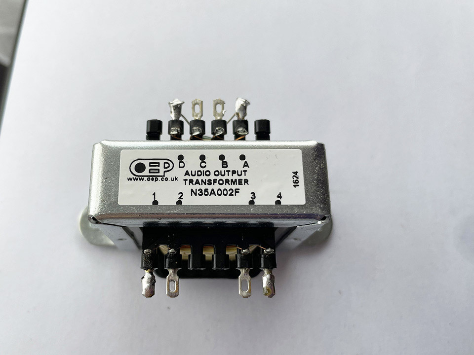
The original output transformer caused some distorion due to an impedance mismatch with the output valve. I’ve now fitted a new Radio Spares transformer, with impedance taps, see below. There’s now some bass and no detectable distorion. That will keep the valve happy… and me! The tuning gearbox is shown on the right. The grease was pretty good but I’ve added a little more. I still have an AGC problem or, I should say, no AGC. That’s next on the list.
27 Aug 2024:
The noise limiter control is the right hand knob below the S meter. According to all the photos I’ve seen online, it shouldn’t be there! For some reason, the double diode limiter valve has been bypassed. There are a couple of burnt resistors on the valve base so I shall look into this at a later date. I now have a temporary (preset) 10K wire wound pot in circuit for the RF gain. Thanks to Graham for posting that to me. For some reason, there’s no AGC so the RF gain control is invaluable! My next job will be to sort out the AGC. I’m hoping it will be something straightforward, such as leaky IF filter capacitors on the AGC rail.
28 Aug 2024:
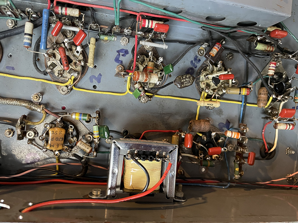
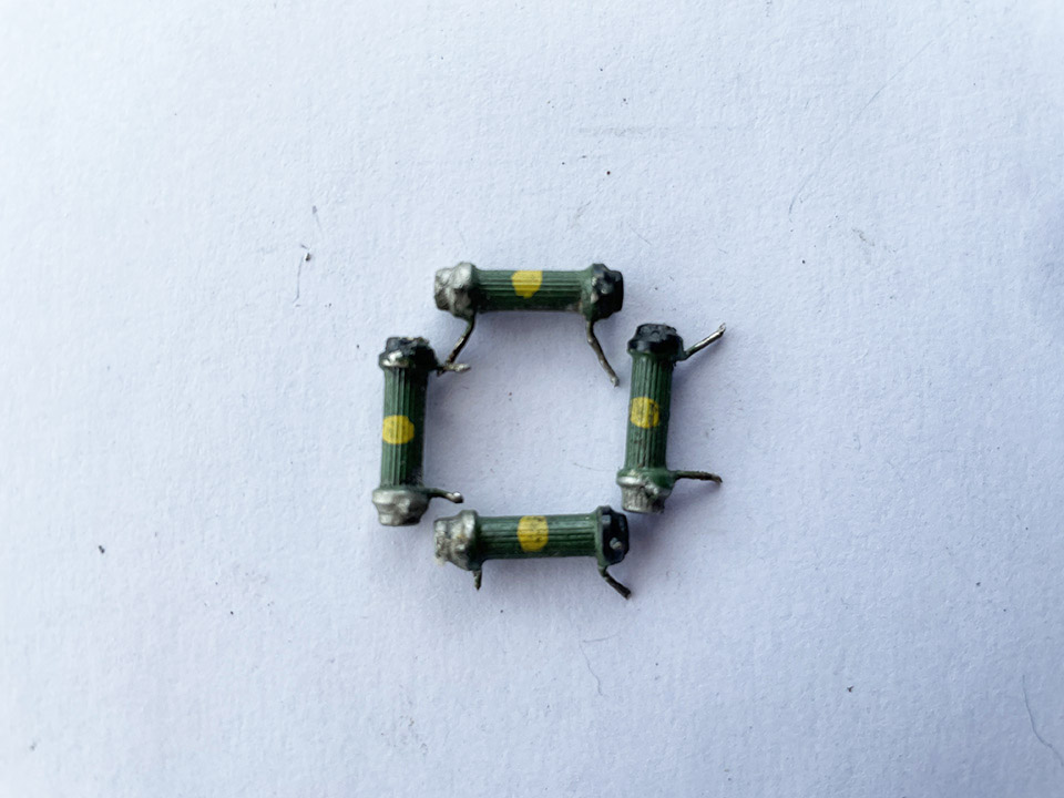 The 470K AGC grid resistors, see photo, had gone high and one was open circuit. Replacing them has solved the lack of AGC problem. The AGC/BFO switch is now wired correctly. The AGC is switched off when the BFO is switched on. I’ve also replaced a few decoupling capacitors which were hidden.
I have two coil packs on the way. One from Mike, 900KHz to 2050KHz, which will give me the rest of the medium wave (AM) band as well as the 160 metre amateur band. Thanks, Mike. The other is coming from eBay, which will give me 3500KHz to 73ooKHz covering 80 metres, the 5MHz frequencies and 40 metres.
29 Aug 2024:
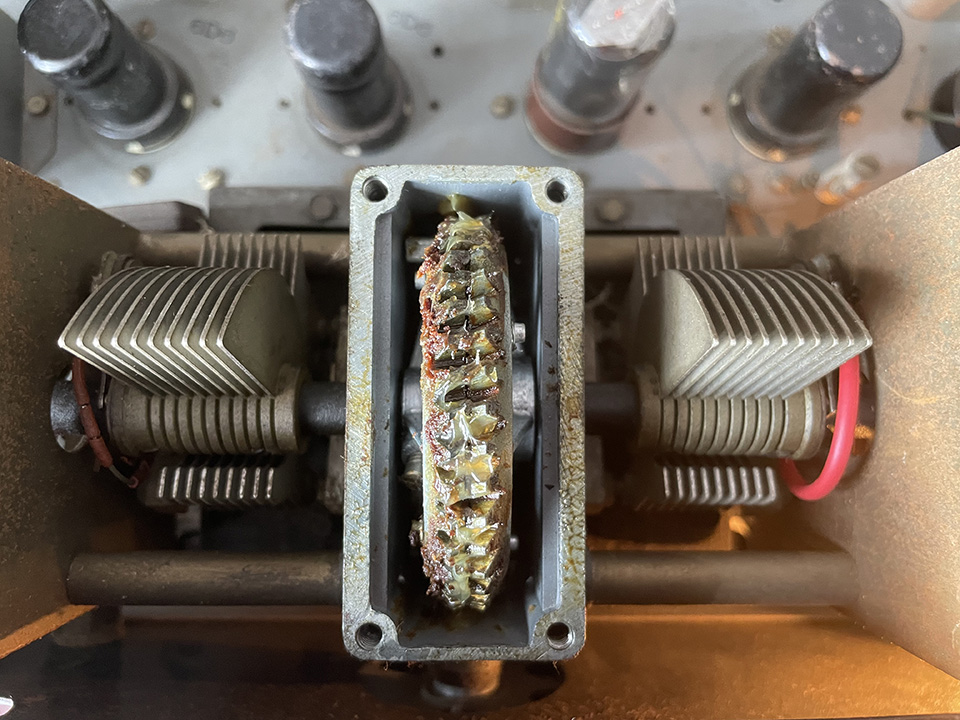
The crystal filter hasn’t been operating properly. I’ve discovered that the quartz crystal is loose in its holder. In the right-hand photo below, you can see the block of quartz crystal. It slides in and out of its holder, barely touching the metal plates either side of the holder. Some careful adjustments (bending) has solved the problem. You may be wondering why the crystal is so thick, looking like a block of ice. This is because the fundamental frequency of a quartz crystal is primarily determined by its thickness. The frequency is inversely proportional to the thickness of the crystal. This means that thinner crystals vibrate at higher frequencies, thicker crystals vibrate at lower frequencies. The resonant frequency of this crystal should be 456KHz but, my NanoVNA reads 460.5KHz.
30 Aug 2024:
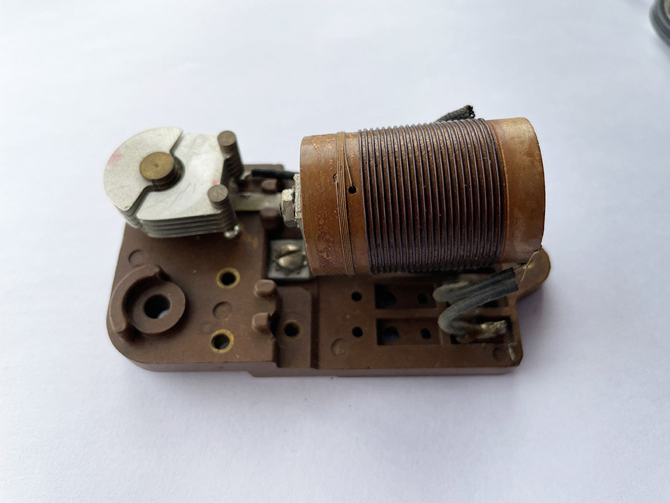
Another two coil packs have arrived. 3.5MHz to 7.3MHz from eBay. Thanks to Mike for the 900KHz to 2050KHz coil pack. I now have full medium wave coverage. Plus, the 160 metre amateur band along with 80m – the 5MHz frequencies and 40M.
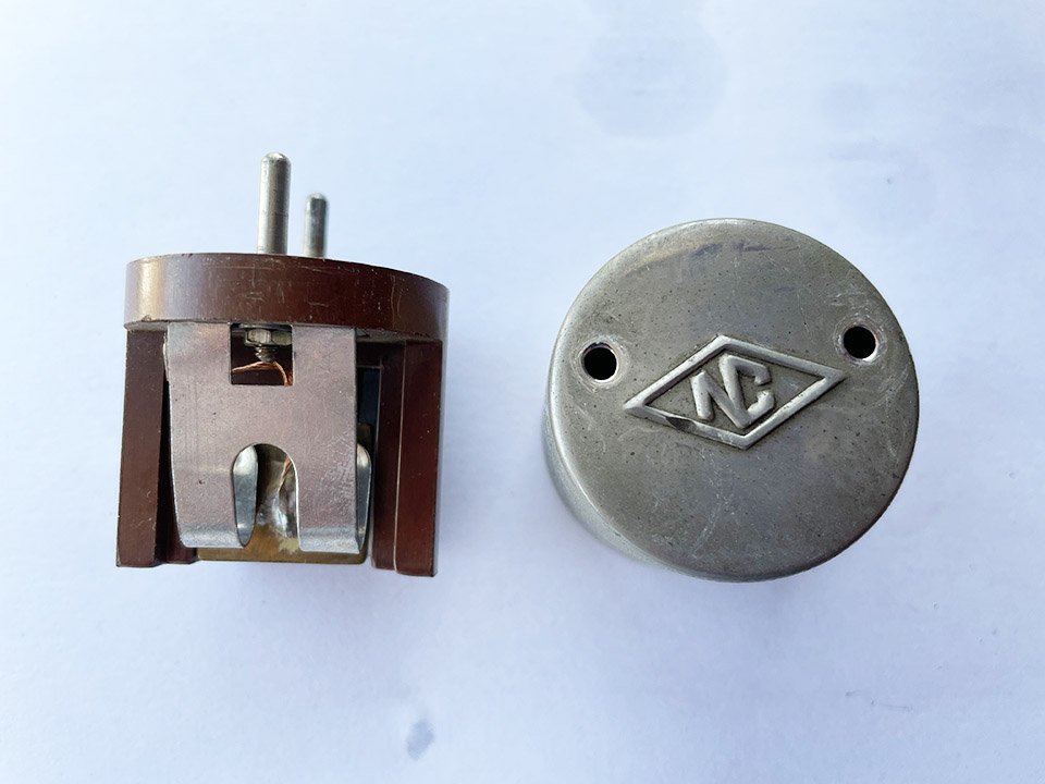
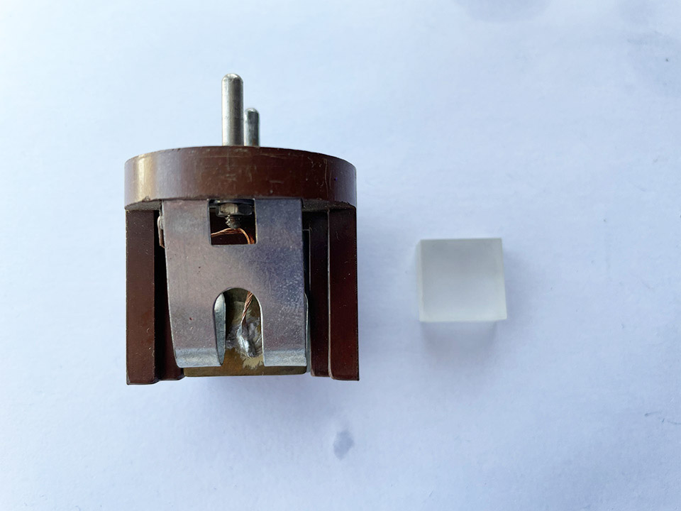
Below is a photo of the aerial coil from the 3.5 to 7.3MHz coil pack.
1 Sept 2024:
I’m now looking into the mixer, which is a heptode – 12SA7 (heptode also known as a pentagrid). After hours of research, I’ve not found one HRO circuit diagram that uses a pentagrid mixer. However, reading an article from the RSGB Bulletin HRO Receiver, I’ve made an interesting discovery. Thanks to Bill from CA for sending me the article. The article describes modifying the mixer stage by replacing the 6C6 pentode (UX6 base) with a 6BE6 heptode or pentagrid (B7G).
My HRO, all octal bases, uses a 12SA7 heptode in the mixer. Was this modification based on the RSGB Bulletin modification or did HRO make the change during production? According to the article, using a heptode results in hardly any change in cathode current with changes in signal grid voltage. Because of this, there will be very little degeneration or regeneration of the of the signal input or the IF output. This is a great advantage over using a pentode.
2 Sept 2024:
A quick signal report. I’m receiving Chichester Hospital Radio, which is 17 miles from my location, on 1431KHz. LPAM stations run up to 1 Watt. It’s noisy, but clearly audible. Also receiving BBC Radio Guernsey on 1116KHz at good strength.
3 Sept 2024:
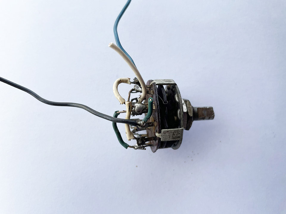
At last, I’ve done away with the messy three way rotary switch which was below the S meter. See phone below. A complete bodge! Tracing the wiring, it would appear that it was something to do with a combination of switching the AGC on/off and S meter on/off. I’ve now replaced it with a simple AGC on off switch, photo on right.
4 Sept 2024:
The RF gain pot has arrived from America. I’ve fitted it and it’s perfect, thanks Chuck! I’ve been using my NanoVNA as a signal generator to check the frequency coverage of the coil packs. The 900KHz to 2050KHz pack actually covers 830KHz to 1900KHz. Why? See video part six for further info.
6 Sept 2024:
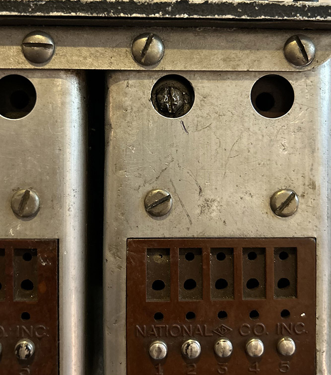
The coil pack I bought online was advertised as tested, working. I suppose it was working, to an extent. I had to realign each section because someone had been at it with a screwdriver… or a crowbar! Look at the damaged screw head in the photo. Why do people do this sort of thing? They’ve gone in with the wrong size screw driver and wrecked the screw head, which probably didn’t need adjusting anyway! Actually, HRO would have been better off using cheese head rather than dome head for the adjustments.
The coil pack was supposed to cover 3.5MHz to 7.3MHz but is was way off frequency. After alignment, it now covers 3.4MHz to 7.6MHz so I can tune around the 41 metre broadcast band. The 40m amateur band is also alive and kicking and, surprisingly, the radio resolves SSB transmissions extremely well.
7 Sept 2024:
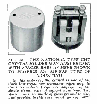 An interesting discovery concerning the crystal filter. Earlier, I talked about the quartz crystal rattling about between the two brass plates. I adjusted the plates so the crystal made contact properly. I was wrong! The photo here is taken from an HRO article. Sorry the text isn’t clear but it reads…
In this instance, the crystal is one of the thick, low frequency-resonator types used in the intermediate frequency amplifier of the signal type of super-heterodyne. The spacer bars are made of glass ground to size and provide, in this case, an air gap of .002″.
This means that the crystal will be loose between the brass plates, which seems odd to me. However, I have put the glass spacers back in the holder, adjusted the filter alignment and the filter works beautifully. Is the quartz crystal relying on the capacitance between the brass plates? I have no idea! I’ll be discussing this in video number seven, so look out for that one.
17 Sept 2024:
I’m impatient, so I’ve put the radio is back in its cabinet. I still have the S meter to sort out… and the noise limiter. But I can work beneath the chassis with the cabinet in place. The dial needs to be removed, cleaned and resprayed, but that will be the last job. I’ve fitted a 1/4 inch jack socket on the rear of the chassis for the loudspeaker. I’ve also fitted a temporary RCA phono socket for the aerial. I really need terminals for balanced or end-fed inputs. That will come later. Plus, I need to build a power supply.
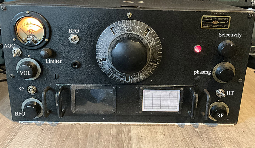
The controls:
Not all switches are in the correct place. This is because models vary and this particular receiver doesn’t appear to have a model number.
The Power Supply:
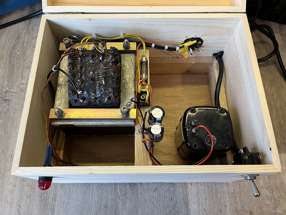
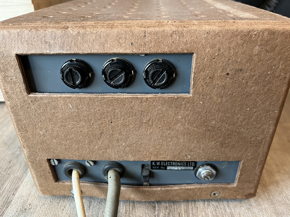
I was running the receiver from a power supply I built for a WS 19 set. However, I’m in the process of finishing off a decent power supply. I couldn’t find an aluminium or steel box to build the power supply in, but I have found a really nice wooden box. Don’t laugh, there’s nothing wrong with wood. In fact, KW Electronics supplied a PSU for their KW Vespa transmitter in a cardboard box!
I’ve also found a fantastic transformer which will do the job perfectly. Lots of different voltages at decent currents. Below is the power supply in its wooden box. I’ll be using the PSU to power the homebrew transmitter as well as the HRO as the transformer is more that man enough. The secondary windings are: two 6.3 volts at 4 amps, one 175 volts at 100mA, one 342-0-342 volts at 238mA, one 420-362-0-362-420 volts at 200mA. I was given the Parmeko choke, which is 10H at 75mA, thanks Martin.
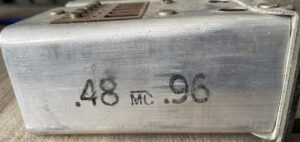
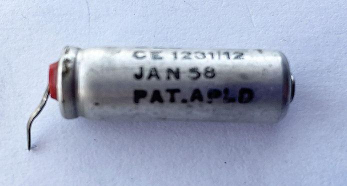
A clue as to the receiver’s age:
At last, I’ve found an original component which is date stamped. January 1958. The image is a little blurred but the date is clearly visible. I’m convinced that this is an original component and not one that’s been added years after the radio’s manufacture. I have often thought as I’ve been working on this receiver that is was assembled during the late 50s or even early 60s. There are so many anomalies, such as all metal valves with no top caps, a triode audio output valve, variable selectivity rather than switched, noise limiter pot below the S meter and so much more. I believe HRO built these receivers well into the late 50s so this might well be from that era.
An anomaly:
The AGC on/off SPST switch has been replaced with a DPDT so that the CW oscillator (BFO) is switched along with the AGC. This is wrong but idea is that the CW oscillator is switched on in the AGC off position. However, it’s been wired so the CW oscillator in running when the AGC is on. This is back to front, but easily corrected. The point is, this shows what a mess someone has made of the receiver. Straightforward fault finding is one thing but, sorting out wiring mistakes at the same time… And all this without the correct circuit diagram! See 28 Aug 2014 above for update.
Another anomaly:
The S meter on off switch should be SPST. Someone has fitted a three way rotary switch in its place. I’ll have to trace the six wires to work out what’s going on. Is there no end to the mess? What else will I discover?
The Noise Limiter:
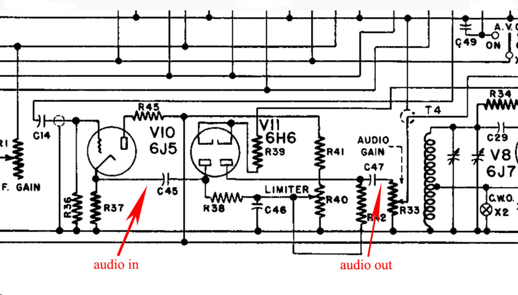
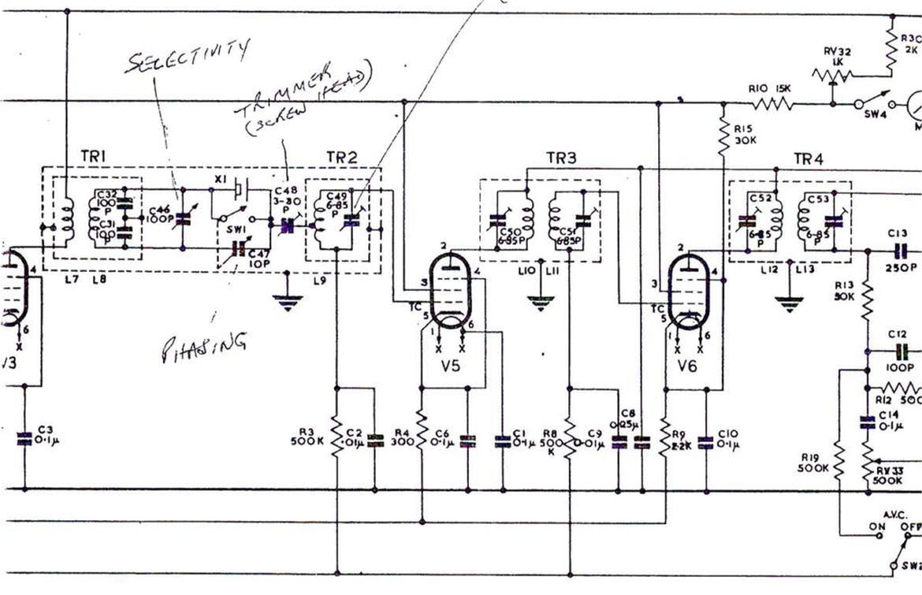
The noise limiter, see circuit below, has been bypassed. C45 has been removed from the diode anode and connected directly to C47 at the top of the audio gain control. Yet another problem to be solved!
The HRO R106 receiver:
A chap in America sent me this circuit diagram. It shows a variable selectivity control rather than a six position switch, which I thought was missing. This circuit is part of the HRO R106 which is very similar to my receiver. In fact, the R106 Mk1 audio output stage uses a pentode. The R106 MK2 uses a triode. My receiver uses a triode so, is mine an HRO R106? The problem is, the R106 with the triode audio output has nine valves, my receiver has eleven.
The US Navy, different coil packs and IF frequency:
One key requirement from the US Navy was for the receiver to cover frequencies between 400 and 500 kHz, a range the standard HRO could not access due to its intermediate frequency (IF) of 456 kHz. To address this, the IF was adjusted to 175 kHz, allowing the receiver to cover a broader frequency range from approximately 200 kHz to 30 MHz.
The Navy also specified that receiver came equipped with seven coils, which were not interchangeable with those of the standard HRO. These coils were distinguishable by two metal plates on the front, which engaged with the locking system, as well as unique stampings on the coil insulators.
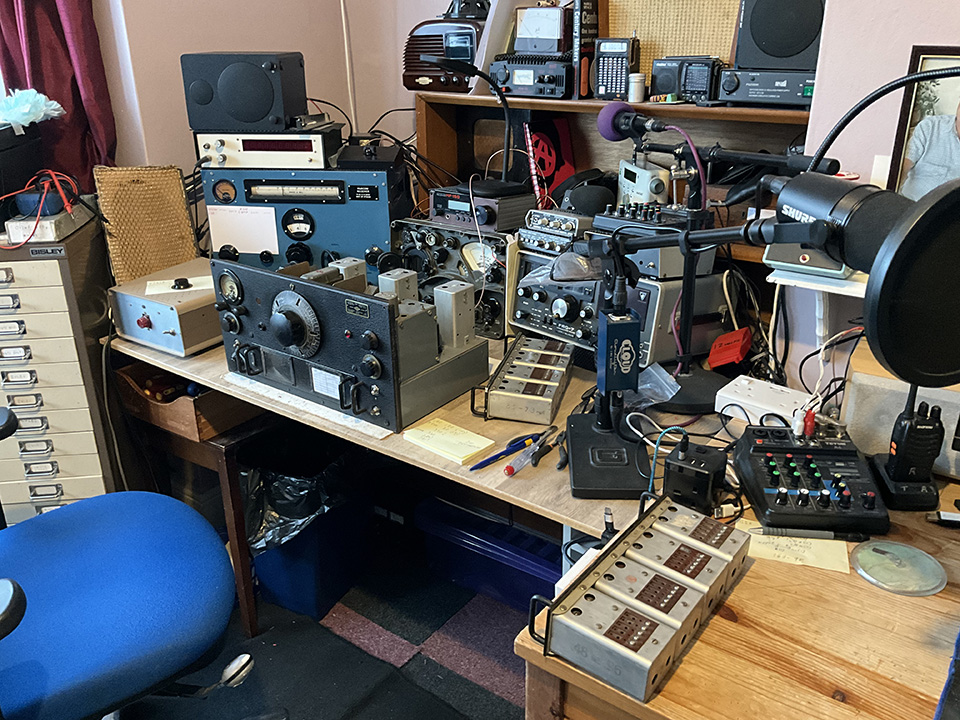
My HRO Workbench:
This was what I called my receiving station. I used the radios for short wave listening, medium wave DXing, but… It’s now become my HRO workbench. I can’t get to my Marconi CR100, the R209, the Yaesu FRG-7, the Lowe HF-150… What a mess!
Service manuals etc:
HRO 5A1 here.
HRO R106 here. Thanks, Ed.
The new HRO instruction manual here.
HRO instruction manual 1939 here.
The RSGB Bulletin HRO Receiver mixer article.
Bletchley Park and the HRO here.
Many thanks to Roy G4WTV, Mike G0JXX, Andy G3UEQ, Graham, Brad and Chuck from the USA, for the parts donated and your help with this project.