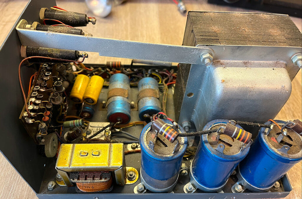
WARNING: High voltages are employed in this type of equipment.
This is a vintage KW MK1 Vespa transmitter. It first appeared on the market in 1965 and was followed in 1966 by the MK2 model. Covering 160 to 10 metres in several bands, it allowed many amateurs to use SSB as well as AM. This one belongs to a friend who asked me to restore it for him. It’s complete with power supply but no microphone. The only thing I don’t like is the aerial connector. It’s a Belling-Lee coax socket. They were bad enough on televisions back in the sixties. To fit them on transmitters… No!
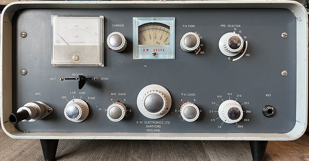
4/12/24:
I’ve checked the power supply and all appears to be intact. The capacitors aren’t bulging or leaking, which is a good sign. Using a Variac, I wound the mains voltage up slowly over a period of time and the power supply didn’t explode. Powering up the transmitter and switching to tune, I used a lightbulb as a dummy load. Watch the video to find out what happened…
KW Vespa MK1. Video part one:
An ealy advert:
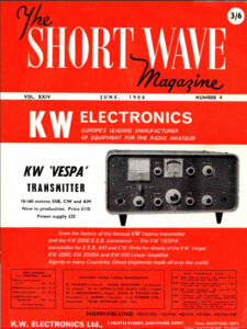 This is the sort of transmitter I could only dream about back in the 1960s. I remember seeing adverts for Heathkit gear along with other well-known manufacturers, all well above my price range. My pride and joy was a WS 19 set bought from GWM Radio for £1-10/-
Having said that, working on old military gear and getting it going was an invaluable experience. While well-off people were buying expensive gear, I was firing up a 52 set with an 813 PA with 3kV on the anode. Much more fun that buying something new and just plugging it in. The same applies today. For example, why buy an expensive ATU when you can build your own? A homebrew ATU will probably be far better than buying a black box containing a few cheap and nasty components. Here is a page dedicated to ATUs.
PA tuning and loading procedure:
Back in the old days, with valve transmitters, tuning and loading the PA properly was important. Set the transmitter to the desired band and frequency. Connect a 50 ohm dummy load and adjust the PA tuning control for a dip in anode current. Bring the meter out of the dip with a loading control. Then, with the PA tuning control, dip the anode current again. Bring it out of the dip again with the loading control. Repeat this procedure until the anode current is suitable for the PA valve. The transmitter is now adjusted for a 50 ohm load. Connect the transmitter to your ATU and a suitable aerial. Adjust the ATU for one-to-one SWR.
Depending on the type of aerial in use and the operating frequency, an ATU might not be necessary. The Pi network in the transmitter will match a range of impedances.
This procedure tunes the PA valve and then loads the valve with the aerial. Dip the anode current as quickly as possible after loading as prolonged high anode current could damage the valve. Some people simply adjust the PA tuning and loading controls for maximum anode current. This isn’t a good idea as too much anode current could ruin the valve.
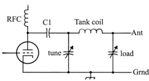
Pi tank circuit:
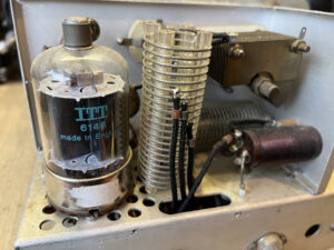
This is the sort of circuit used in the KW Vespa. RFC is an RF choke. HT is taken to the valve anode via the choke to prevent RF flowing into the HT rail. The choke allows DC to pass but blocks RF. C1 prevents HT flowing into the aerial. C1 allows RF to pass but blocks DC. The tune variable capacitor tunes the valve anode. The load variable capacitor loads the valve. The aerial is the load. This is a basic diagram. The tank coil would normally be tapped along its length. The taps will either selected by the band switch or a separate rotary switch. The KW Vespa PA valve and tank coil are shown on the right.
Transmitter power:
As a matter of interest, when refering to the power of valve transmitters, we refer to the DC input. This is calculated from the HT voltage applied the anode of the PA valve and the anode current. Power (in Watts) = V (volts) x I (amps). So 500 Volts at 100 mA will be 50 Watts DC input.
The chassis:
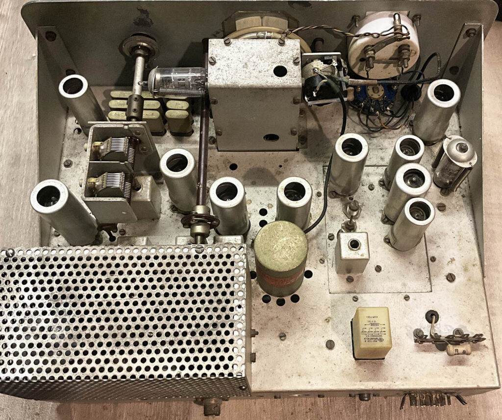
There are some brown stains on the chassis so I’m wondering whether it’s been in a nicotine atmosphere. After all, just about everyone smoked back in the 1960s. None of the crystals are missing, all valves are in situ, the tuning gang vanes haven’t been damaged… all that is needed is a good clean.
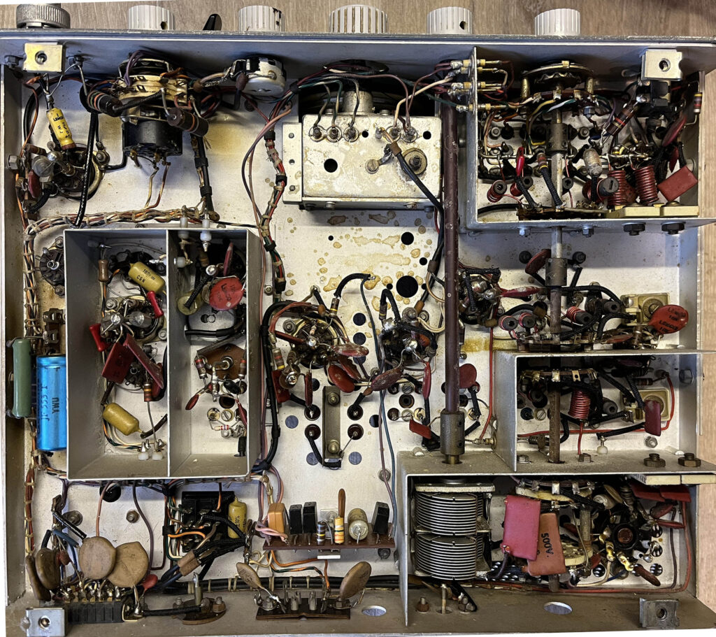
Beneath the chassis:
Most of the capacitors are silvered mica so they will be fine. I’ve cleaned the pots and switches, lubricated the variable capacitor bearings and earthing contacts, cleaned all valve bases, and everything is looking good.
The power supply:
Everything seems to be intact, albeit dusty. I ran the power supply for a while and the electrolytics remained cold, which is a good sign. Ideally, they should be replaced as they’re around sixty years old. I’ll give it some thought.
Here is a very interesting article about Kokusai Mechanical Filters by Graham, G4EUK.
Manual KW-Vespa-MK2-manual. Thanks to ED from California. Anyone got the MK1 manual?
Article. Notes-on-the-KW-Vespa-Transmitter. Short Wave Magazine 1968.
The KW-Vespa-Transmitter-RSGB-Bulletin 1966.

